In-Situ Metallography
In-Situ Metallographic testing is carried out to determine the conditions with respect to any degradation or abnormality present in the equipment due to the operational conditions.
Pressure and temperature plays an important role in degradation mechanism for alloys like plain carbon, medium carbon and high alloy steels used in different process plant application. Principally, addition of alloying elements increases ability to withstand severe process demands by generating proper metallurgical conditions in an alloy. Various NDT Inspections are carried out on operating plants for various reasons like, condition assessment, life assessment to avoid failure and for safe and reliable operation. Due to critical assessment requirement of plant components, microstructural evaluation of the component has become powerful tool.
The technique of in situ metallography involves location selection, mechanical grinding &polishing / electrolytic polishing, electrolytic etching or chemical etching, replication and microstructural observation. The kit of in-situ metallography comprises of portable grinder, light grinder with variable speed controller, electrolytic etcher/polisher, microscope and variety of consumables. The consumables can be listed as self-adhesive polishing papers of different grit size, self-adhesive velvet cloth, solvents, water bottles, diamond paste, and suspended alumina, electrolytes and replica films
DAMAGE MECHANISMS THAT ARE DETECTED THROUGH MICROSTRUCTURESTUDIES
Damage mechanisms that are common to a variety of industries including refining and petrochemical, pulp and paper, and fossil utility are covered in this Section.
The principle deterioration mechanisms that could be detected by using in situ metallographic techniques are the microstructural degradation like Spheroidization of pearlite, creep, hydrogen attack, carburization, grain boundary oxidization and em-brittlement of microstructure etc. Aspects of each will be considered in turn. Depending upon the alloys used and microstructure conditions with expertise on interpretations skills many other mechanisms and damages can be predicted.
DEGRADATION OF PEARLITE:
Microstructures are designated with respect to the microstructural degradation. This may be only a diffusional degradation or creep damage, which would have taken place because of high temperature exposure of the component. Prolonged high temperature exposure of carbon and low- alloy steels renders pearlite colonies into spheroids. However, addition of alloying elements like Chromium and Molybdenum retards spherodisation.
In Carbon steels & Cr-Mo steels are subjected to diffusional degradation by sequential degradation of pearlite followed by formation of carbides (spherodisation). The spherodisation of pearlite reduces the mechanical strength of the steel and alloys steels. When complete spherodisation occurs it needs replacement of the component.
In materials such as austenitic stainless steels carbide precipitation at grain boundaries leads to depletion of matrix chromium resulting in loss of corrosion resistance.
Various methods of classifying the boiler steel microstructures are followed. A widely accepted Classification is described by
Designated Level Vs Description of Microstructure
(For Diffusion degradation level)
Level IL: Minimal tendency to break up of bainite/pearlite.
Level IIL: Incipient break of bainite& isolated precipitated carbides in ferrite.
Level IIIL: Distinct break up of bainite/pearlite. Ferrite grows darker due to carbide precipitation
Level IVL: Bainite/pearlite structure visible. Distinct grain boundary carbides and dot like Precipitates in ferrite.
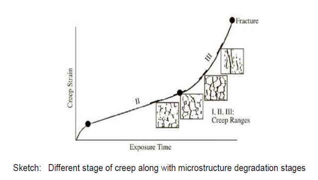
CREEP DAMAGE:
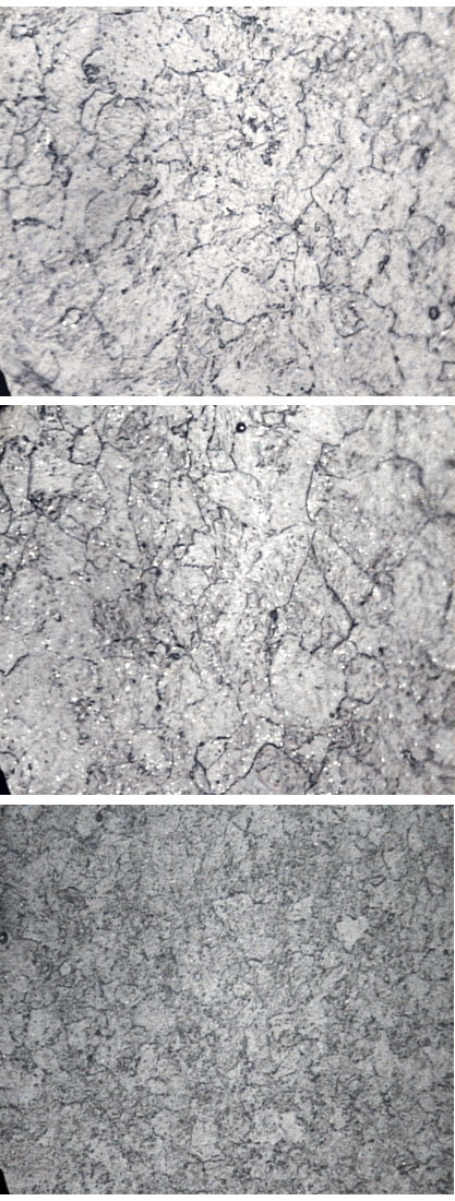
Creep is one of the most serious high temperature damage mechanisms. It involves time dependent deformation and high temperature creep cracking, develops at grain boundaries in engineering components that fail over an extended time. These include boiler super-heater and other components operating at high temperature, petrochemical furnace and reactor vessel components and gas turbine blades. At higher temperatures, with local overheating, deformation may be localized with large plastic strains and wall thinning. At somewhat lower temperatures and under correspondingly higher stress level. The fracture is eventually intergranule in nature. Classification of creep damage in the components exposed to creep range has been made using the largely qualitative approach based on distribution of creep voids and micro cracks observed by in situ metallography. The three stages of creep and associated microstructure degradations are represented in the sketch given below. Basic guidelines for evaluation of creep damage and provide judgment on the inspection intervals are given in Table. In situ metallography used in conjunction with semi quantitative tools like hardness measurements indicating loss of tensile strength would permit remaining life assessment studies on components undergoing creep damage. A point worth noting at this juncture is that the chrome Molly steels are liable to fail by creep in a short time by displaying spheroidzation of carbides but with little void formation.
HIGH TEMPERATURE OXIDATION:
Under highly oxidizing atmosphere grain boundary oxidization takes place that penetrate inside. Thus, the thickening of grain boundaries in carbon steels can be seen with etching response during insitu metallography.
DECARBURISATION:
The carbon in the steel can react with oxygen and in the atmosphere at high temperature to get decarburization of the surface. The loss of carbon in the surface of steel can be found out from microstructure examinations.
GRAIN COARSENING:
Grain coarsening takes place with prolonged high temperature exposure which decreases the strength of the steel. This can be easily noticed by microstructure examination.
EMBRITTLEMENT AND CARBURIZATION
Embrittlement from precipitations arise in a number of different ways for instance, sigma phase formation in austenitic stainless steels maintained at high temperature or cycled through the critical temperature range of 565 to 989 oC causes loss of ductility and embrittlement. Ferritic stainless steels may be subjected to embrittlement phenomenon when held at or cooled over the temperature range 550 to 400oC. If the temperature conditions are likely to lead to such effects, metallographic checks are employed after extended exposure prior to an unexpected rupture developing. Cracks can initiate from the brittle carburized layer, which has little resistance to bending. This can be detected by metallography. Normally the damages are compared with the normal microstructures on comparison basis to judge the extent of degradations.
SPECIMEN PREPARATION TECHNIQUE -
PROCEDURE – EXAMINATION OF REPLICA
WRITE TO US
Quality Network Pvt Ltd.
Works
No. 10, II Cross Street, Kalaimagal Nagar,
Ekkattuthangal, Chennai - 600032
CONTACT US
Registered Address
#38/GA, Shoreham, 5th Avenue, Besant Nagar,
Chennai – 600 090
CONTACT DETAILS
Phone: +91 44 3551 0355