Phased Array Inspection/ TOFD Inspection
Ultrasonic phased arrays have proven to be a very appropriate inspection technique for weld inspections, especially encoded arrays with linear scanning. The flexibility of phased arrays allows them to be tailored to almost any weld profile and predicted defects. Besides showing the normal advantages of phased arrays for welds (high speed, reduced costs, full data storage, increased productivity), the paper will illustrate sample weld inspection Scan Plans and coverage. In addition, some codes have been adapted to the use of phased arrays, so these inspection techniques are effectively controlled and approved. TOFD (Time-Of-Flight Diffraction) can be added for improved detection capability and better sizing. Back diffraction also offers significant benefits for accurate sizing.
Phased arrays have significant advantages over conventional inspection techniques: flexibility, high speed, lower costs (under many conditions), full data storage for auditing, and significantly increased productivity (for volume inspections).
1. What is a phased array system?
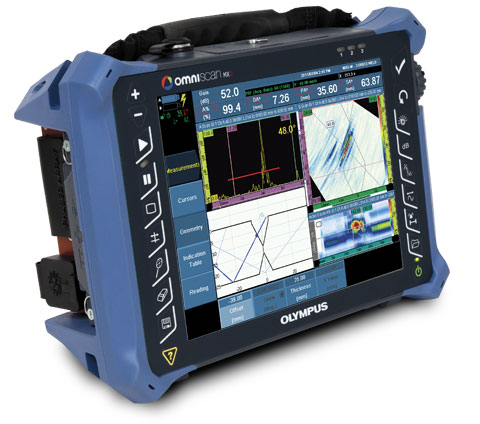
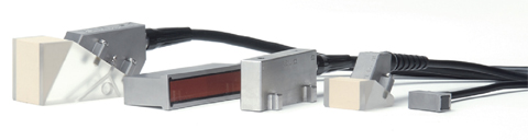
Conventional ultrasonic transducers for NDT commonly consist of either a single active element that both generates and receives high frequency sound waves, or two paired elements, one for transmitting and one for receiving. Phased array probes, on the other hand, typically consist of a transducer assembly with from 16 to as many as 256 small individual elements that can each be pulsed separately. These may be arranged in a strip (linear array), a ring (annular array), a circular matrix (circular array), or a more complex shape. As is the case with conventional transducers, phased array probes may be designed for direct contact use, as part of an angle beam assembly with a wedge, or for immersion use with sound coupling through a water path. Transducer frequencies are most commonly in the range from 2 MHz to 10 MHz. A phased array system will also include a sophisticated computer-based instrument that is capable of driving the multi-element probe, receiving and digitizing the returning echoes, and plotting that echo information in various standard formats. Unlike conventional flaw detectors, phased array systems can sweep a sound beam through a range of refracted angles or along a linear path, or dynamically focus at a number of different depths, thus increasing both flexibility and capability in inspection setups.
2. How do they work?
In the most basic sense, a phased array system utilizes the wave physics principle of phasing, varying the time between a series of outgoing ultrasonic pulses in such a way that the individual wave fronts generated by each element in the array combine with each other to add or cancel energy in predictable ways that effectively steer and shape the sound beam.
This is accomplished by pulsing the individual probe elements at slightly different times. Frequently the elements will be pulsed in groups of 4 to 32 in order to improve effective sensitivity by increasing aperture, which reduces unwanted beam spreading and enables sharper focusing. Software known as a focal law calculator establishes specific delay times for firing each group of elements in order to generate the desired beam shape, taking into account probe and wedge characteristics as well as the geometry and acoustical properties of the test material. The programmed pulsing sequence selected by the instrument's operating software then launches a number of individual wave fronts in the test material. These wave fronts in turn combine constructively and destructively into a single primary wave front that travels through the test material and reflects off cracks, discontinuities, back walls, and other material boundaries like any conventional ultrasonic wave. The beam can be dynamically steered through various angles, focal distances, and focal spot sizes in such a way that a single probe assembly is capable of examining the test material across a range of different perspectives. This beam steering happens very quickly, so that a scan from multiple angles or with multiple focal depths can be performed in a small fraction of a second.
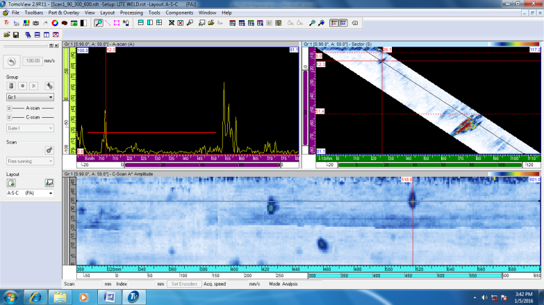
The returning echoes are received by the various elements or groups of elements and time-shifted as necessary to compensate for varying wedge delays and then summed. Unlike a conventional single element transducer, which will effectively merge the effects of all beam components that strike its area, a phased array transducer can spatially sort the returning wavefront according to the arrival time and amplitude at each element. When processed by instrument software, each returned focal law represents the reflection from a particular angular component of the beam, a particular point along a linear path, and/or a reflection from a particular focal depth. The echo information can then be displayed in any of several formats.
Where are phased array systems used?
Ultrasonic phased array systems can potentially be employed in almost any test where conventional ultrasonic flaw detectors have traditionally been used. Weld inspection and crack detection are the most important applications, and these tests are done across a wide range of industries including aerospace, power generation, petrochemical, metal billet and tubular goods suppliers, pipeline construction and maintenance, structural metals, and general manufacturing. Phased arrays can also be effectively used to profile remaining wall thickness in corrosion survey applications.
The benefits of phased array technology over conventional UT come from its ability to use multiple elements to steer, focus and scan beams with a single transducer assembly. Beam steering, commonly referred to sectorial scanning, can be used for mapping components at appropriate angles. This can greatly simplify the inspection of components with complex geometries. The small footprint of the transducer and the ability to sweep the beam without moving the probe also aids inspection of such components in situations where there is limited access for mechanical scanning. Sectorial scanning is also typically used for weld inspection. The ability to test welds with multiple angles from a single probe greatly increases the probability of detection of anomalies. Electronic focusing permits optimizing the beam shape and size at the expected defect location, thus further optimizing probability of detection. The ability to focus at multiple depths also improves the ability for sizing critical defects for volumetric inspections. Focusing can significantly improve signal-to-noise ratio in challenging applications, and electronic scanning across many groups of elements allows for C-Scan images to be produced very rapidly.
WRITE TO US
Quality Network Pvt Ltd.
Works
No. 10, II Cross Street, Kalaimagal Nagar,
Ekkattuthangal, Chennai - 600032
CONTACT US
Registered Address
#38/GA, Shoreham, 5th Avenue, Besant Nagar,
Chennai – 600 090
CONTACT DETAILS
Phone: +91 44 3551 0355